Key Takeaways
- Learn how RCP types and classes influence structural strength and performance
- Understand how standards guide proper selection and installation
- Apply best practices to achieve long-lasting, compliant infrastructure
Selecting the right reinforced concrete pipe (RCP) can define the success and longevity of your project. Whether you’re managing stormwater systems, culverts, or sanitary sewers, each pipe class, shape, and joint type affects structural performance and installation efficiency. Understanding RCP types, strength classes, and TIS standards ensures you choose materials that meet both design requirements and regulatory expectations.
You work in an environment where precision matters. Knowing how load classes, bedding conditions, and reinforcement methods influence durability allows you to make informed decisions from the start. By aligning pipe specifications with soil conditions and hydraulic needs, you reduce maintenance demands and extend service life.
Contents
1. Understanding Reinforced Concrete Pipe (RCP)
3. RCP Classes, Strength, and Standards
4. How to Choose the Right RCP for Your Project
- Matching Pipe Class to Project Load
- Choosing the Right Pipe for Drainage vs. Sewerage
- Reinforced vs. Non-Reinforced: When to Use Each
5. Joints, Connections, and Watertightness
6. Installation Practices and Site Considerations
- Trench Excavation and Bedding
- Backfill and Haunch Support
- Minimum Cover and Construction Loads
- Soil Type and Density Requirements
7. Durability, Inspection, and Maintenance
- Durability Factors and Service Life
- Chlorides, Sulfate, and Corrosive Environments
- Hydraulic Capacity and Performance
- Inspection and Quality Control
Understanding Reinforced Concrete Pipe (RCP)
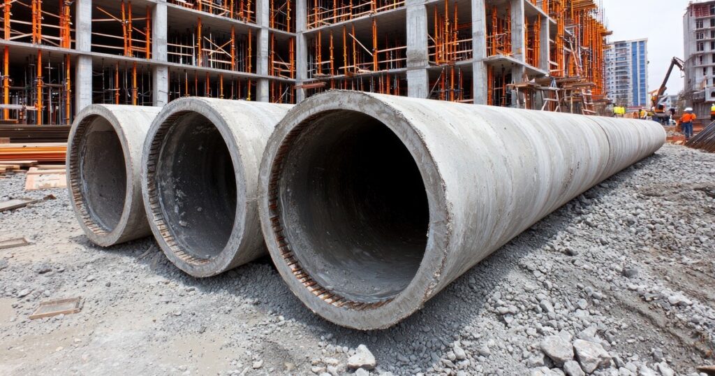
Reinforced concrete pipe provides a durable and load-bearing solution for subsurface water conveyance and structural drainage systems. Its design combines concrete’s compressive strength with steel reinforcement, allowing you to manage heavy loads and long-term exposure conditions more effectively than non-reinforced alternatives.
Definition and Composition
Reinforced concrete pipe (RCP) consists of concrete reinforced with steel bars or wire mesh to resist tensile stresses. The concrete matrix provides compressive strength, while the reinforcement prevents cracking under bending or external loads.
You can find RCP in diameters ranging from 300 mm to over 3,600 mm, depending on project requirements. Wall thickness, reinforcement type, and concrete strength vary by pipe class and design standard, such as ASTM C76 or AASHTO M 170.
Unlike non-reinforced concrete pipe (NRCP), which relies solely on concrete strength, RCP’s steel reinforcement enables it to handle traffic loads, soil pressure, and hydraulic forces in demanding environments. The pipe’s joints are typically designed as tongue-and-groove or rubber gasketed to ensure watertight performance in storm or sanitary systems.
RCP’s expected service life often exceeds 75 years with proper installation and maintenance, making it a preferred choice for long-term infrastructure.
Common Applications in Infrastructure
You use reinforced concrete pipe in systems where strength, durability, and hydraulic efficiency are critical. Typical applications include:
- Storm sewers and culverts for roadway and urban drainage
- Sanitary sewers for wastewater conveyance
- Irrigation or utility conduits in agricultural and municipal projects
RCP performs well under high cover depths and heavy traffic loads, making it suitable for highways, airports, and industrial zones. Its rigid structure minimizes deformation, maintaining grade and alignment over decades.
In contrast, non-reinforced concrete pipes are limited to shallow or low-load conditions. For most public works, you select RCP because it meets strength classifications from Class I to Class V, ensuring compliance with TIS, ASTM, and AASHTO standards for structural and hydraulic performance.
Types and Shapes of RCP
Reinforced concrete pipe (RCP) comes in several geometric forms to meet structural and hydraulic requirements. The type and shape you select depend on flow conditions, available cover, and space constraints within the project site.
Circular RCP
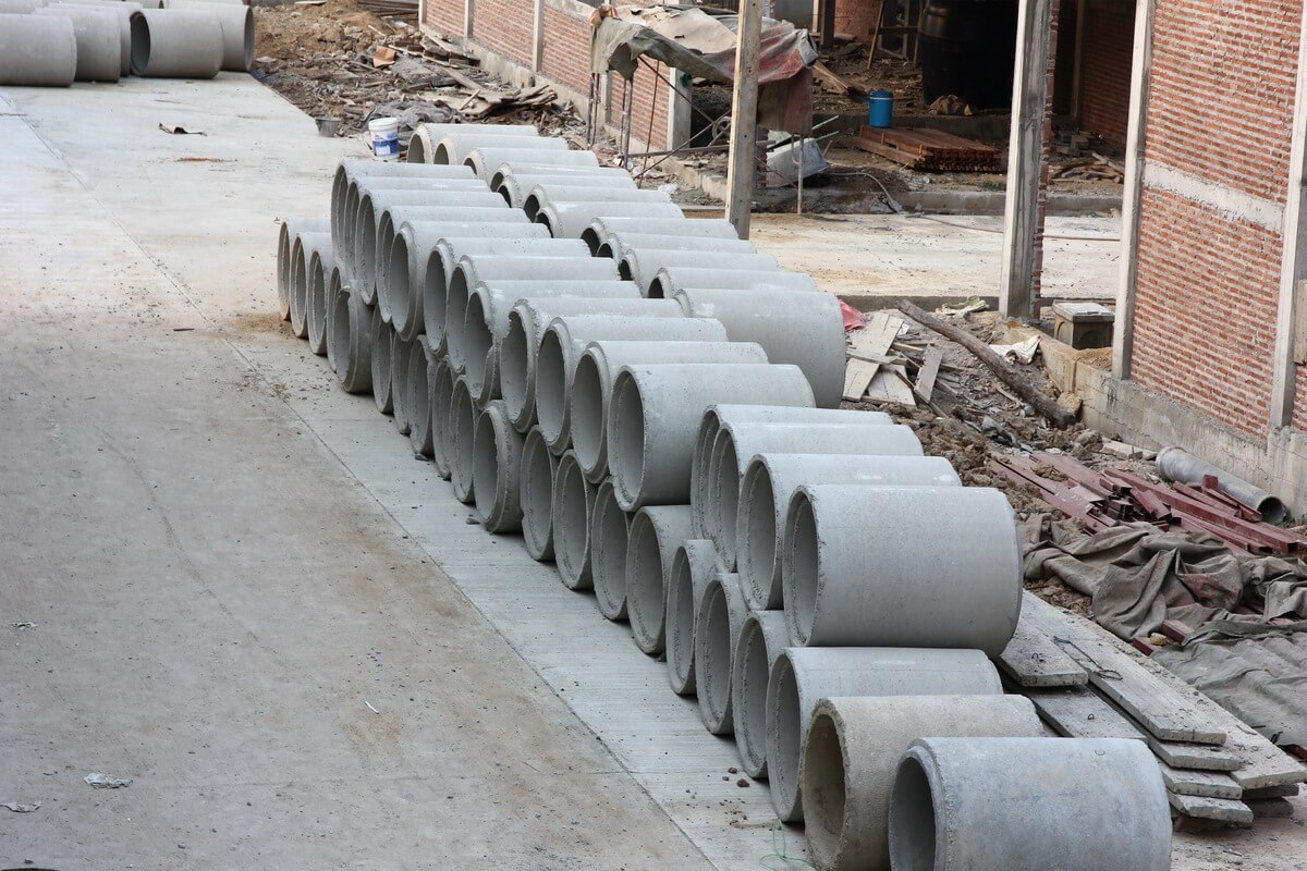
Circular RCP is the most common and widely manufactured form of concrete pipe. You typically use it for storm drains, sanitary sewers, and culvert systems because of its uniform strength and predictable hydraulic behavior.
Standard diameters range from 300 mm (12 in.) to 3600 mm (144 in.), with lengths often between 2.4 m and 2.5 m. Larger diameters can be made for major conveyance systems or outfalls.
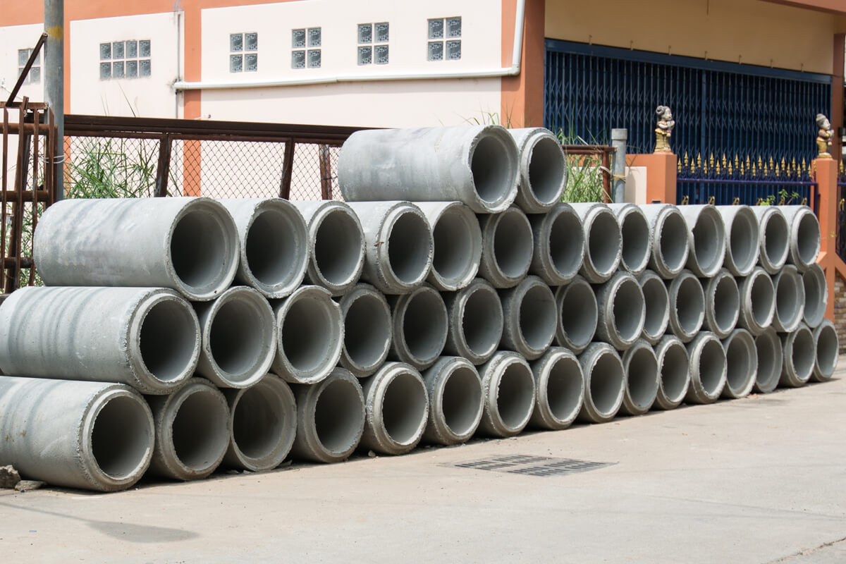
Circular pipes provide equal strength in all directions, making them efficient under uniform soil loading. They are designed and tested to ASTM C76, AASHTO M170, and related standards.
When installed with proper bedding and compaction, circular RCP achieves a high bedding factor, improving load capacity and reducing risk of structural failure under heavy cover conditions.
Elliptical and Arch RCP
Elliptical and arch RCP are used where vertical clearance is limited but hydraulic capacity must be maintained. You often install these shapes under roads, railways, or shallow embankments where cover depth cannot accommodate a full circular section.
These pipes are classified as Horizontal Elliptical (HE) or Vertical Elliptical (VE) depending on the orientation of the major axis. Typical dimensions range from 450 mm × 300 mm up to 2400 mm × 1800 mm.
Elliptical RCP provides similar flow performance to circular pipe of equivalent area but allows reduced installation height. Arch RCP, with a flatter invert, performs well in open-channel and culvert applications where low flow velocities or fish passage are design concerns.
Designers must account for nonuniform load distribution and ensure reinforcement placement matches the load direction.
Specialty and Custom RCP
Specialty and custom RCP configurations address unique site or hydraulic conditions. You may specify jacking pipe, flared-end sections, slotted drain pipe, or precast fittings for transitions, bends, and manhole connections.
Manufacturers can produce nonstandard diameters, thicker wall sections, or integrated gasket joints to meet project-specific performance requirements. These modifications follow applicable ASTM, AASHTO, or TIS standards to ensure structural reliability.
Custom shapes are often used in complex drainage networks, utility crossings, or combined sewer systems where standard pipe geometry cannot accommodate alignment or flow constraints.
Proper coordination between the engineer, contractor, and supplier ensures that specialty RCP meets both hydraulic and structural design criteria without compromising durability or ease of installation.
RCP Classes, Strength, and Standards
Reinforced Concrete Pipe (RCP) strength depends on its class, wall design, and compliance with recognized standards. You select the proper class and thickness based on structural load, installation conditions, and governing specifications such as ASTM C76 and Thailand Industrial Standards (TIS) 128-2560.
Pipe Classes and D-Load Ratings
RCP is manufactured in five primary classes—Class I through Class V—each designed to withstand increasing loads. You determine the appropriate class by evaluating the D-load rating, which represents the external load the pipe can support per unit of inside diameter.
| Condition | Description | Common Treatment |
|---|---|---|
| Mild crowding | Slight overlap of teeth | Clear aligners or retainers |
| Moderate crowding | Teeth rotated or tilted | Braces or aligner systems |
| Severe overcrowding | Significant overlap or misalignment | Tooth extraction and braces |
The D-load test measures the pipe’s performance under three-edge bearing conditions. Engineers and inspectors use this value to verify compliance with design requirements before installation. Selecting the correct class ensures the pipe resists soil pressure and live loads without structural failure.
Wall Thickness and Strength Considerations
Wall thickness directly influences pipe strength and durability. A thicker wall increases the pipe’s ability to resist external loads and internal pressure but also adds weight and cost. Manufacturers design wall sections based on load class, diameter, and bedding conditions specified by the engineer.
For instance, a Class III pipe typically has a thinner wall than a Class V pipe of the same diameter. The steel reinforcement pattern—single cage or double cage—also affects load capacity. You should verify that the pipe’s wall design meets both structural and hydraulic requirements.
Proper bedding and compaction beneath the pipe are critical. Even a high-strength pipe can fail if support conditions are poor, so site preparation must match the assumptions used in design calculations.
TIS and ASTM Standards
RCP in Thailand typically follows TIS 128-2560, which aligns closely with ASTM C76. Both standards define material composition, reinforcement type, wall design, and minimum D-load values for each class. Compliance ensures uniform quality and predictable performance across different manufacturers.
Under these standards, each pipe undergoes compressive strength and hydrostatic tests to confirm structural integrity. You should request certification documents from the pipe manufacturer verifying that the product meets both TIS and ASTM requirements.
Adhering to these standards helps ensure compatibility with local specifications and guarantees that your project meets regulatory and safety expectations.
How to Choose the Right RCP for Your Project
Selecting the correct reinforced concrete pipe (RCP) depends on structural load demands, intended use, and environmental conditions. You must evaluate pipe class, application type, and whether reinforcement is necessary to ensure long-term performance and compliance with relevant standards.
Matching Pipe Class to Project Load
RCPs are classified by their load-bearing capacity, typically from Class I to Class V under ASTM C76 or equivalent TIS standards. Each class defines the pipe’s ability to withstand external loads from soil cover, traffic, or structural weight.
Use Class I–II for light-duty applications such as small drainage channels or non-traffic areas. Class III–IV suits medium to heavy traffic conditions, including municipal storm drains or culverts. Class V is designed for high-load environments like highways or industrial sites.
Always verify the design earth cover, live load, and bedding conditions before selection. A misclassified pipe can lead to cracking or joint failure. Consulting structural load tables and TIS 1162 or ASTM C76 test results ensures your chosen class meets both design and safety requirements.
Choosing the Right Pipe for Drainage vs. Sewerage
Drainage and sewerage systems impose different operational demands on RCP. For stormwater drainage, prioritize hydraulic capacity and resistance to external pressure. Smooth internal surfaces and watertight joints—such as rubber-ring or tongue-and-groove joints—improve flow and reduce infiltration.
For sanitary sewerage, chemical resistance becomes critical. Wastewater can contain corrosive gases and acidic compounds that degrade unprotected concrete. In these cases, use lined RCP with epoxy, polyethylene, or PVC coatings to prevent corrosion and extend service life.
Consider maintenance accessibility and potential surcharge conditions. Proper joint selection and alignment testing reduce leakage and infiltration, preserving system integrity over decades of use.
Reinforced vs. Non-Reinforced: When to Use Each
Reinforced concrete pipe (RCP) uses embedded steel reinforcement to resist tensile and shear stresses, making it suitable for deeper installations or heavy surface loads. You should specify reinforced types when soil cover exceeds 1.5 meters or when subjected to vehicle or structural loads.
Non-reinforced concrete pipe (NRCP), while less expensive, fits shallow or low-load applications such as small irrigation or field drains. It relies on the concrete’s compressive strength alone.
Use the table below for quick reference:
| Pipe Type: RCP | |
|---|---|
| Typical Use | Roadways, sewers, culverts |
| Load Capacity | High |
| Recommended Depth | >1.5 m |
| Pipe Type: NRCP | |
|---|---|
| Typical Use | Field drains, minor ditches |
| Load Capacity | Low–Medium |
| Recommended Depth | <1.5 m |
Selecting between the two depends on your site’s structural conditions, budget, and service life expectations.
Joints, Connections, and Watertightness
Proper joint selection and assembly ensure that reinforced concrete pipe systems remain watertight, structurally sound, and durable under varying soil and load conditions. The materials and methods used for sealing influence performance, installation time, and long-term maintenance.

Types of Concrete Pipe Joints
Concrete pipe joints are designed to provide soil-tight or water-tight connections depending on project requirements. You typically choose between rigid and flexible joints.
Rigid joints rely on cement mortar or similar materials to create a fixed seal that allows little to no movement. They are common in gravity-flow systems where alignment remains constant.
Flexible joints, often using rubber gaskets, accommodate minor deflection and ground movement without leakage. These are preferred in installations subject to settlement or vibration.
Common joint configurations include:
| Joint Type: Spigot and Socket | |
|---|---|
| Description | Spigot end fits into the socket of the next pipe |
| Typical Use | General drainage and sewer lines |
| Joint Type: Tongue and Groove | |
|---|---|
| Description | Interlocking edges for alignment and strength |
| Typical Use | Culverts and storm drains |
| Joint Type: O-Ring or Gasketed Joint | |
|---|---|
| Description | Uses rubber gasket for watertight seal |
| Typical Use | Pressurized or infiltration-sensitive systems |
Each joint type must meet applicable standards, such as ASTM C443 or AASHTO M198, to ensure performance consistency.
Rubber Gaskets and Sealing Methods
Rubber gaskets provide flexibility and watertightness by forming a compressed seal between pipe ends. You install them in a preformed groove on the spigot or within the bell.
The gasket’s material—commonly neoprene, EPDM, or SBR rubber—must resist chemical attack, temperature variation, and aging. Proper lubrication during assembly reduces friction and prevents gasket displacement.
When correctly installed, gasketed joints can withstand internal pressures and external infiltration. They also simplify maintenance since the joint can tolerate small misalignments.
You should verify gasket dimensions and compression levels before installation. Inadequate seating or over-compression can lead to leaks or joint failure. Periodic inspection during construction helps maintain uniform quality.
Cement Mortar and Joint Assembly
Cement mortar joints rely on a rigid bond between pipe sections. You apply a mortar band around the spigot before inserting it into the socket, ensuring full contact and a continuous seal.
Use a 1:2 or 1:3 cement-to-sand ratio with clean, well-graded sand. The joint should be cured properly to prevent shrinkage cracks that could allow infiltration.
Mortar joints are suitable for low-pressure or gravity systems where joint movement is minimal. They provide structural continuity and resist shear forces transmitted through the pipeline.
During assembly, clean all contact surfaces to remove dust and laitance. Fill any voids immediately after joining to maintain full strength. Consistent workmanship is essential for achieving the required watertightness and durability in service.
Installation Practices and Site Considerations
Proper installation of reinforced concrete pipe (RCP) depends on stable trench conditions, uniform bedding, controlled backfill placement, and adequate soil support. You must account for load distribution, soil density, and cover depth to ensure long-term structural integrity and hydraulic performance.

Trench Excavation and Bedding
Excavate the trench to a width that allows safe working space and proper compaction of sidefill. The trench bottom must provide uniform support without voids or high points. Over-excavation should be corrected with compacted granular material, not left unfilled.
Provide a bedding layer of granular material or crushed stone typically 100–150 mm thick. This bedding distributes loads evenly and minimizes point contact with the pipe barrel.
Maintain grade control using a laser or level instrument. The bedding surface must match the design slope and remain free of debris and standing water. Avoid placing pipes directly on unprepared soil or rock.
When installing bell-and-spigot joints, shape the bedding to accommodate the bell end so the pipe rests fully along its barrel. This prevents joint stress and misalignment during assembly.
Backfill and Haunch Support
The haunch zone—between the bottom of the pipe and the springline—provides critical load-bearing support. You must compact this area carefully and uniformly on both sides to prevent differential settlement.
Use granular or well-graded soil meeting project specifications. Avoid large stones, frozen materials, or organic matter. Compact the haunch material in layers not exceeding 150 mm thick using mechanical tampers suited for confined spaces.
After haunching, place sidefill and initial backfill up to the top of the pipe. Compact each layer to the specified density, often 90–95% of maximum dry density per ASTM D698 or AASHTO T99.
Do not drop backfill directly over the pipe or use heavy compactors until sufficient cover is achieved. Proper haunch and sidefill compaction reduce deflection and help the RCP act as a composite structure with the surrounding soil.
Minimum Cover and Construction Loads
Minimum cover protects the RCP from construction and live loads before final surface layers are placed. The required depth depends on pipe diameter, class, and anticipated wheel or equipment loads.
As a guideline, maintain at least 300 mm to 600 mm of compacted cover during construction traffic. For large-diameter or heavy-load conditions, consult the manufacturer’s tables or AASHTO design criteria for specific cover requirements.
If heavy construction equipment must cross the trench, increase the temporary cover or use load-distribution mats. Never allow vehicles to pass over exposed or partially backfilled pipe.
Monitor cover thickness throughout construction to prevent overstressing the pipe wall or joints. Insufficient cover can cause cracking or alignment shifts that compromise long-term performance.
Soil Type and Density Requirements
Soil classification directly affects pipe performance and required compaction effort. Cohesive soils (CL, CH) provide moderate support but require careful moisture control, while granular soils (GW, GP, SW, SP) offer superior drainage and compaction characteristics.
You should verify soil type through field testing or laboratory classification before installation. Adjust bedding and backfill materials if native soils do not meet design strength or drainage criteria.
Compaction should achieve the specified density—commonly at least 90% of Standard Proctor for bedding and 95% for haunch and sidefill areas. Use moisture conditioning to reach optimum compaction.
In unstable or saturated soils, consider trench stabilization methods such as geotextile separation layers or over-excavation with imported granular fill. Proper soil selection and density control ensure uniform pipe support and reduce the risk of settlement or joint leakage.
Durability, Inspection, and Maintenance
You must account for material quality, exposure conditions, and construction practices to ensure long-term performance of reinforced concrete pipe (RCP). Proper design, inspection, and maintenance help prevent deterioration, maintain hydraulic function, and extend the service life of buried infrastructure.

Durability Factors and Service Life
Durability depends on the concrete mix, reinforcement protection, and environmental exposure. You should specify concrete with a low water-cement ratio and adequate cementitious content to reduce permeability. Denser concrete limits the ingress of moisture and aggressive ions that cause corrosion.
Reinforcement cover plays a critical role. Maintain the minimum cover specified by AASHTO M 170 or local standards to prevent steel corrosion. Inadequate cover accelerates deterioration, especially in aggressive soils.
Design life for RCP commonly exceeds 75 to 100 years when materials meet specification and installation follows best practices. You should also consider loading conditions, bedding quality, and joint integrity since these factors influence cracking and long-term strength.
Routine evaluation of pipe sections for cracking, spalling, or joint separation allows early identification of durability issues before they compromise structural performance.
Chlorides, Sulfate, and Corrosive Environments
You must assess soil and groundwater chemistry before installation. High concentrations of chlorides promote reinforcement corrosion, while sulfates attack the cement paste, leading to expansion and cracking.
Use Type II or Type V cement for sulfate resistance and include supplementary cementitious materials such as fly ash or slag to improve chemical durability. In chloride-rich environments, increase concrete cover or apply protective coatings to the interior surface.
When RCP is exposed to industrial effluents, saline water, or deicing salts, specify corrosion-resistant reinforcement or nonmetallic alternatives. For extreme conditions, consider internal liners made of PVC or HDPE to isolate concrete from aggressive agents.
Periodic testing of soil pH and ion concentration helps verify that protection measures remain effective throughout the service life.
Hydraulic Capacity and Performance
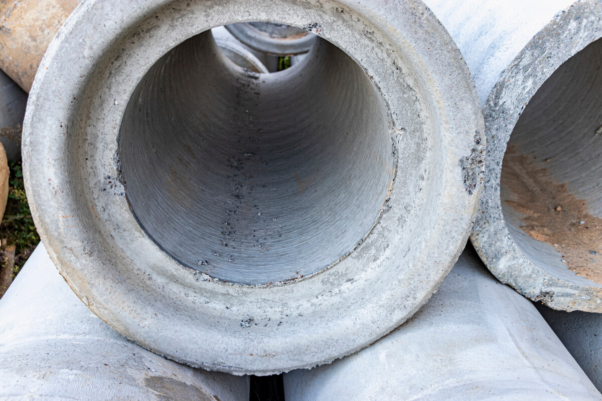
Hydraulic capacity determines how efficiently RCP conveys water under design flow conditions. Smooth interior finishes and accurate joint alignment reduce head loss and maintain flow efficiency.
You should verify that the pipe slope, diameter, and Manning’s roughness coefficient meet project design criteria. Sediment buildup, joint offsets, or surface roughness can reduce capacity and cause upstream ponding.
Regular cleaning and inspection of culverts and storm drains preserve hydraulic performance. In areas with variable flow or abrasive materials, select higher pipe classes (such as Class III or IV) to resist wear and maintain structural integrity.
Proper bedding and backfill compaction prevent deformation that could affect hydraulic grade lines or invert elevations.
Inspection and Quality Control
Inspection ensures compliance with MoDOT, AASHTO, or project-specific standards. You should perform visual inspection of each lot for cracks, honeycombing, or dimensional deviations before acceptance.
Inspectors verify markings for pipe class, manufacturer, and date of production. Pipes showing fractures through the wall, open texture, or defective joints must be rejected.
| Inspection Item: Pipe Markings | |
|---|---|
| Acceptance Criteria | Must match AASHTO M 170 |
| Action if Noncompliant | Reject pipe |
| Inspection Item: Cracks > 0.01 in. width or >12 in. length | |
|---|---|
| Acceptance Criteria | Not permitted |
| Action if Noncompliant | Reject pipe |
| Inspection Item: Wall Thickness | |
|---|---|
| Acceptance Criteria | Within 5% of design |
| Action if Noncompliant | Reject if under limit |
| Inspection Item: Load Test (Three-Edge Bearing) | |
|---|---|
| Acceptance Criteria | Meets D-load requirement |
| Action if Noncompliant | Reject if below |
Engineers may require three-edge bearing tests or compressive strength tests to confirm structural performance. You should document all inspections and maintain traceability through lot numbers and test reports.